
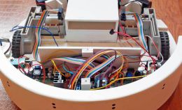
Наткнулся в интерене на скетч для изготовления цифрового осциллографа на Arduino. Скетч был для дисплея нокиа, но под рукой был только OLED дисплей на протоколе i2c. По тому пришлось немного переписать код.
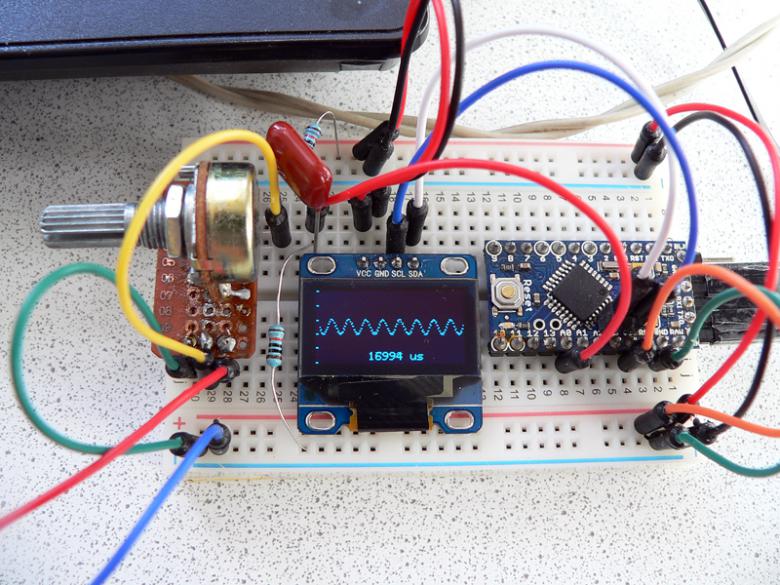
Осциллограф работает с напряжениями +-5 вольт. Читает частоту сигналу до 500 Герц.
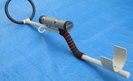
Сборка выполнена на Arduino Pro Mini, но любая другая тоже пойдет.
A0 - будет принимать сигнал. Для регулировки чувствительности была собрана небольшая схема: два подтягивающих резистора по 10 k на плюс и минус, через конденсатор 100 pF покдлючен к "щупу" через переменный резистор. Так удалось избавиться от лишних наводок самой Arduino и расширить диапазон измерений по току.
SCL, SDA - подключаются на каждой плате к своим каналам, которые поддерживают протокол i2c.
VVc, GND соотвественно.
Для цифрового измерения уровней предусмотрены кнопки управления:
8 - сброс настроек
9, 10 - управление
#include <SPI.h>
#include <Adafruit_GFX.h>
#include "Adafruit_ILI9340.h"

#define _sclk 13
#define _miso 12
#define _mosi 11
#define _cs 10
#define _dc 9
#define _rst 8

Adafruit_ILI9340 tft = Adafruit_ILI9340(_cs, _dc, _rst);

/********************************************/

#define SCREENWIDTH         320
#define SCREENHEIGHT        240
#define CHARWIDTH           5
#define CHARHEIGHT          7
#define AXISWIDTH           (2 + 1)                   // axis will show two-pixel wide graph ticks, then an empty column
#define VISIBLEVALUEPIXELS  (SCREENWIDTH - AXISWIDTH) // the number of samples visible on screen
#define NUMVALUES           (2 * VISIBLEVALUEPIXELS)  // the total number of samples (take twice as many as visible, to help find trigger point

#define TRIGGER_ENABLE_PIN       2  // set this pin high to enable trigger
#define SCREEN_UPDATE_ENABLE_PIN 3  // set this pin high to freeze screen

byte values[NUMVALUES];           // stores read analog values mapped to 0-127 (can't store 0-1024 in one byte)
byte values2[NUMVALUES];          // stores read analog values mapped to 0-127 (can't store 0-1024 in one byte)
byte* frontBuffer = values;
byte* backBuffer = values2;
int pos = 0;                      // the next position in the value array to read
int count = 0;                    // the total number of times through the loop
unsigned long readStartTime = 0;  // time when the current sampling started
int lastStart = 0;                // the sample at which drawing started last time (need to know this to clear the old line properly)

// Used by vsprintf.
char buffer[32];

/********************************************/

// Draws a printf style string at the current cursor position.
// Note that existing contents of buffer are used to overwrite
// the previous display with black to clear it first - a shameful
// hack indeed
void displayln(int x, int y, const char* format, ...)
{
  // Erase previous text
  tft.setTextColor(ILI9340_BLACK);
  tft.setCursor(x, y);
  tft.println(buffer);

  va_list args;
  va_start(args, format);
  vsprintf(buffer, format, args);
  va_end(args);

  tft.setTextColor(ILI9340_YELLOW);
  tft.setCursor(x, y);
  tft.println(buffer);
}

// Draws the graph ticks for the vertical axis
void drawAxis()
{
  byte div = SCREENHEIGHT / 5;
  for (int x = 0; x < 2; x++) {
    for (int y = 0; y < 6; y++) {
      tft.drawPixel(x, y * div, ILI9340_WHITE);
    }
  }
}

// Draws the sampled values
void drawValues()
{
  int start = 0;
  float mag = SCREENHEIGHT / 128.0; // 128 because sample values are 0-127

  if ( true || digitalRead(TRIGGER_ENABLE_PIN) ) {
    // Find the first occurence of zero
    for (int i = 0; i < NUMVALUES; i++) {
      if ( backBuffer[i] != 0 ) {
        // Now find the next value that is not zero
        for (; i < NUMVALUES; i++) {
          if ( backBuffer[i] == 0 ) {
            start = i;
            break;
          }
        }
        break;
      }
    }
    // If the trigger point is not within half of our values, we will
    // not have enough sample points to show the wave correctly. In this
    // case, just draw the same line in white to let the user know that
    // the values are old (also prevents the screen from scrolling sideways,
    // and takes less time)
    if ( start >= VISIBLEVALUEPIXELS ) {
      for (int i = 0; i < VISIBLEVALUEPIXELS; i++) {
        tft.drawPixel(i + AXISWIDTH, SCREENHEIGHT - 1 - (frontBuffer[i + lastStart] * mag), ILI9340_WHITE);
      }
      return;
    }
  }

  // clear the old line and draw the new
  for (int i = 0; i < VISIBLEVALUEPIXELS; i++) {
    tft.drawPixel(i + AXISWIDTH, SCREENHEIGHT - 1 - (frontBuffer[i + lastStart] * mag), ILI9340_BLACK);
    tft.drawPixel(i + AXISWIDTH, SCREENHEIGHT - 1 - (backBuffer[i + start] * mag), ILI9340_GREEN);
  }

  // swap sample buffers
  byte* tmp = backBuffer;
  backBuffer = frontBuffer;   fr

  lastStart = start;

}

// Shows the time taken to sample the values shown on screen
void drawFrameTime(unsigned long us)
{
  displayln(SCREENWIDTH/2 - 4*CHARWIDTH, SCREENHEIGHT - 1.5*CHARHEIGHT, "%ld us", us);
}

/********************************************/

void setup() {

  // Set up the display
  tft.begin();
  tft.setRotation(1);
  tft.setTextSize(1);
  tft.fillScreen(ILI9340_BLACK);
  drawAxis();

  buffer[0] = 0;

  pinMode(TRIGGER_ENABLE_PIN, INPUT);
  pinMode(SCREEN_UPDATE_ENABLE_PIN, INPUT);

}

/********************************************/

// http://extremeelectronics.co.in/avr-tutorials/using-the-analog-to-digital-converter/
void sampleValues() {
  // set the analog reference (high two bits of ADMUX) and select the
  // channel (low 4 bits).  this also sets ADLAR (left-adjust result)
  // to 0 (the default).
  ADMUX = (DEFAULT << 6) | (0 & 0x07);

  ADCSRA &= ~(ADPS0 | ADPS1 | ADPS2);

  boolean digi = false; // set this to true if you are only interested in digital signals, to get MUCH more speed

  if ( digi ) {
    for (int i = 0; i < NUMVALUES; i++) {
      backBuffer[i] = PINC;
      delayMicroseconds(5); // change this as necessary to alter the duration of the sampling pass
    }
    for (int i = 0; i < NUMVALUES; i++) {
      backBuffer[i] = backBuffer[i] > 0 ? 64 : 0; // a value of 64 is half-way in the 0-127 range we are using
    }
  }
  else {
    for (int i = 0; i < NUMVALUES; i++) {

      //start conversion
      _SFR_BYTE(ADCSRA) |= _BV(ADSC);

      // ADSC is cleared when the conversion finishes
      while (bit_is_set(ADCSRA, ADSC));

      // we have to read ADCL first; doing so locks both ADCL
      // and ADCH until ADCH is read.  reading ADCL second would
      // cause the results of each conversion to be discarded,
      // as ADCL and ADCH would be locked when it completed.
      uint8_t low  = ADCL;
      uint8_t high = ADCH;

      // Combine the two bytes, shifting so that the result is in 0-127 range.
      // You could also do 0-255 range - I can't rememember why I didn't do that,
      // but I think it had something to do with my screen being only 240 pixels
      // high... looking at it now though, I don't see why that would have mattered.
      backBuffer[i] = (high << 5) | (low >> 3);

      delayMicroseconds(60); // change this as necessary to alter the duration of the sampling pass
    }
  }

}

/********************************************/

void loop() {

  if ( !digitalRead(SCREEN_UPDATE_ENABLE_PIN) ) {

    readStartTime = micros();

    sampleValues();

    unsigned long totalSampleTime = (micros() - readStartTime) / 2; // Divide by 2 because we are taking twice as many samples as are shown on the screen

    // Display the data on screen
    drawValues();
    drawFrameTime(totalSampleTime);

  }
}